Sunday, December 31, 2023


13007 Power Transistor, Faulty Diodes and a Capacitor Found in Self Made LED Porch Light

This is a generally available Power Supply that can take around 2A load usually used for LED Serial Lights. I had bought one along with a ready made strip of LED lights for use in my Car Porch. This has been working fine for the last two years. But suddenly went dead, tripping the MCB. So removed it and checked what went wrong, after thorough cleaning. I had provided grill to prevent any gecko doing any exploration. Though the grill was having very small pores, the unit was almost packed with very small dead insects, which find its way through.

On opening and checking the components on the board, I could see that the fuse was cracked; all the four rectifier diodes were short along with the 13007 transistor. The tank capacitor, 33/450V was showing zero ESR and on removing it, I could see that it was rusted and corroded at one pin, due to leakage. These were indications of high voltage surge and moisture formation. Replaced the defective components and checked for any more defects and could not find any.

Since exact size of fuse was not available, used a slightly large one, covering it with a protective sleeve and marking its value on top of it. Powered the PS through a series bulb and found it to be working. So assembled it back and retested it.


Plugged it back on the car porch and checked it again.


These are the defective components:


Monday, December 25, 2023

PS3 REPAIRED


PS3 With Red Light And Beeping Sound Repaired


An American friend of mine brought me this PS3 for repair. It belongs to his two kids and recently, the machine was not working the way it should. The moment it was powered on, it is supposed to change from red light into green but instead, it was only getting red light flashing and a beeping sound then shuts off.


This is a self check at start up and seems like something inside this machine

causing the self check to find something wrong there.


It is an old PS3 but taking it apart is very easy and as seen in the photo just take this parts off and I will be able to see the main board.


The parts were off and I am getting closer to the main board which I think it is the main cause of the problem here.

Very dusty board and if you look closely to the bottom left side of the board I could see something spilled on board and I was not happy to see that.

It looks and smells like coffee spilled here.


More spilled stuff here as well and the more I see of this the more I get nervous and the chance of getting this fixed is very slim.

That looks very bad and seems like someone tried to clean it up but instead made it worse since the thermal past is spread all over the board and it is not supposed to be like that.

I started to clean the board and making sure all the thermal paste is off these parts and after all this cleaning was done, I decide to reflow the main two IC’s because I checked online about his fault and everyone recommended to do this process.


To my surprise, after all the cleaning, reflowing the main two IC’s, adding the fresh thermal paste and then putting all back together it actually worked.


Yes, it worked but my question is how long it is going to last? I informed the customer and he was ok with whatever it happens because he is planning to get a new PS4 or PS5 for his children.


Friday, December 15, 2023


                               ELETRICALS AND ELECTRONICS:

                                             SERVICES BEING OFFERED


                                                     [1] MAINTAINANCE:

                                                    [ 2] REPAIRES:

                                                    [3] TROUBLESHOOTING

                                                    [4] INSTALLATIONS:

                                                    [5] SCHEMITIC DIAGRAMS INTERPRETATIONS

                                                    [6] DESIGNING CIRCUITS

                                                    [ 7] TESTING COMPONENTS


                                 MANDATORIES:

                                                    [1] THIORIES:

                                                    [2] PRACTICALS:

                                TOPICS:

                               CIRCUITS ANALYSIS

                                                     [ 1] RESISTANCE

                                                     [ 2] VOLTAGE

                                                     [3] CURRENT

                                             CIRCUITS COMPONETS

                                                   [ 1]   RESISTORS

                                                    [ 2]   TRANSISTORS

                                                   [ 3]   INDUCTORS

                                                  [4]      DIODES

Introduction and Basics of Electronic Circuit Design                                          

Designing an electronic circuit begins on the breadboard (protoboard). The bed board is a thin plastic rectangular construction base to which electronic components are soldered. The soldered connections are not permanent and can be removed and placed again and again within reason. The construction of a breadboard subsequently turns it into what is known as a PCB, often used in computations, signal amplification, and data transfer.

The interconnections on a PCB connect the soldered components. Charge flows from the positive terminal throughout the interconnection loops to the negative terminal.

Note, Q3 and Q4 in the figure below are complementary, NPN and PNP respectively. This circuit works well for moderate power audio amplifiers. For an explanation of this circuit see “Directly coupled complementary-pair,” 

Ch. 4.

REFRIGERATOR NOT COOLING REPAIRED


To those who wish and interested to practice the electrical and electronics, servicing and repairs I request them to join us and gain knowledge and skills in troubleshooting repairs and servicing the  electronics equipment.


  TROUBLESHOOTING,REPAIR AND SERVICING

TVS

WASHING MACHINE

REFRIDGERATOR

HOME THEATRES SYSTERM

RADIOS

PROJETORS

DESTOPS

CCV SECURITY SYSTEM

ELECTRIC DRYERS

ELECTRIC OVENS

MICROWAVES

ELECTRICAL WORKS, INSTALLATIONS


a. Refrigerator not cooling

The refrigerator not cooling but all function are working normal including the compressor are also running as well.  You also may find a refrigerator cooling at freezer point but in fridge not generating cold at all. But first I will deal with not cooling issues.


The refrigerators comprise: the compressor

                                                               Condensers

                                                               Evaporators

                                                              Expansion valve


Lets me starts explaining how did I done to reinstall the refrigerator back to working normal.

The following are the images of the compressor inside the refrigerator

The work of the compressor is to circulates the refrigerant throughout the system and adds push air to the warm of a circuits. The compressor is the heart of the refrigerator and it plays a very huge role in the refrigerators system. This is how it look.


Checking everything and found are good condition then weld pipe on charging line and prepare the refrigerant. You should identify the appropriate refrigerant type of required for your refrigerators…. refrigerants R-134a and R-600a.


Recharged then tested and it was fine. Conclusions fixing the refrigerators is very easy job. 


                        BLOG: electronicsrepairtech.blogspot.com

                        EMAIL: dicksonmuchoki@gmail.com 


Saturday, December 9, 2023

DENON AVR REPAIRED

 Is DENON AVR Model X-500 Prone To Fungus Attacks And Rusting

Those of you who have read my previous articles on servicing same model might know the reason for my question. For those who have not, here

I received the same model from a different customer living in my home town with the complaint that it just blinks after switching on, which the customer also knew was a protection mode.

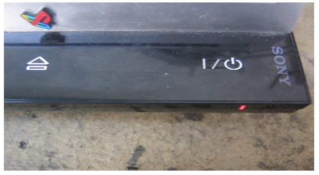
I am only giving the image of the model number plate, to show that it is a different set with a different serial number. I am skipping insertion of other images of inside as it will be a repetition.

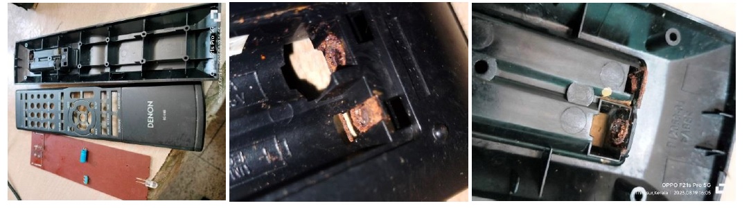
After dismantling the whole set and subjecting it to thorough cleaning of every part, I took up the remote control for rectification, as it had rusted battery contact springs:

I had to clean the area thoroughly and literally dig out the rusted broken spring from its groove. 
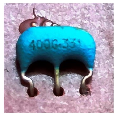
After replacing the spring and putting the battery, and also replacing the capacitor on it, the remote did not work, even though I had cleaned all the contacts too using IPA. Then I replaced the crystal, upon which the remote started working very well.


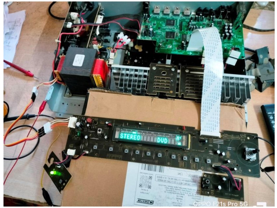
Why did I take up this first? Because, controlling the system through manual mode was very difficult, when 
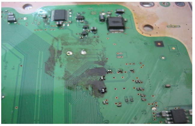
sets are dismantled and connected externally for check-up. As the display was dim, I dismantled the front panel and was not surprised to see the condition inside:  


I cleaned the board thoroughly using IPA. Removed the display and cleaned the legs carefully, as the pins were very thin and likely to break, and replaced all the electrolytic capacitors on this board. Then when I tested, the display was found very healthy and responded to dim commands.

After providing extension wires and connecting the amplifier board externally like how I did in the case (3) link given above, I applied power and saw the serial bulb lighting up indicating high current drawn. I switched off and discharged the tank capacitors and looked for the trouble maker. When I checked the output transistors of the amplifier one by one, I saw two transistors short in one channel. So, I removed them. Still the short was present. (Short between ground and + rail) Then traced it to its speaker protection relay, which was dead short between one pole and one way! I have never seen a relay shorting like this before in my whole years’ experience!

Replaced the transistors and relay after checking every part in that area for any short or open and reconnected the board externally and applied power. This time there was no problem and it worked well. The probable cause for failure was leaky transistor which might have drawn high current shorting the relay. That’s how we also got a thermal error, as the transistor might have been exceeding the temperature limit. Anyhow, I let the set run for several hours before closing it.

You can have a look at the number of pages printed to study the circuit diagrams for easy trouble shooting and the number of minimum components that were replaced in the set, due to the fact that the customer did not have a large budget for the service. 

Anyhow, I fit the set back and delivered it to the customer, after he saw its full functions at my home.

He was so happy to get the set back to working condition. Mission accomplished with great satisfaction getting added to the collection!

Charger power supply fixed


Makita Charger Repair


I got this dead charger from another repair shop in town that was not successful in getting this charger fixed. The guy explained that he opened the device and looked for a fault but somehow he was not able to repair it.


That is a very expensive charger and the guy wanted it repaired as soon as possible.

As you can see there were no bulging capacitors or anything wrong with it when I scanned it with my naked eye.


I powered up the device through a current limiter and the light bulb stayed dim which is an indicator of no short in circuit. I powered it through 220 AC volts and checked for voltage reading at the main capacitor but there was none.

If you look at the photo above you would see a marked area and on the top corner you would also see a dark burnt spot and what confirmed this loose connection is when I powered the device up, I could hear a zap sound coming from that area.


The common sense here is to re solder this spot and get it over with but the moment my solder iron tip touched that part, the connection on that line collapsed on two of these pins.

I used wires to reconnect these two pins (sorry no photo) and soldered them down to the board.

I powered on the device and as expected, the power green light came on flashing and according to the user manual that I found online; is normal and that is a sign that the device is ready to charge the battery when attached to the charger.

The repair was done in less than twenty minutes. I called the guy to come and pick up his device who was really shocked that it did not take long to get this charger fixed.


Email: dicksonmuchoki@gmail.com

Phone no: +254718814978 / +254735149318

  The following are repairs and services we do proving to our customers: washing machines                                : Fridges      ...